Developer Offer
Try ImaginePro API with 50 Free Credits
Build and ship AI-powered visuals with Midjourney, Flux, and more — free credits refresh every month.
AI Drones Revolutionize Aircraft Safety Inspections
Introduction
Aircraft inspection is the critical process of examining an aircraft to ensure it meets safety regulations and standards. Aircraft exteriors are prone to damage from debris, hail, bird strikes, and lightning, leading to issues like pits, scratches, cracks, and corrosion. Traditional inspections can take 1 to 7 days, causing significant downtime and profit loss for airlines. Faster inspection methods are needed to minimize these impacts.
Common aircraft inspection types include:
- Pre-flight inspection: A visual check of the aircraft's exterior and control systems before every flight.
- Annual inspection: A thorough check of systems, components, and maintenance records.
- Phase inspection: Performed at regular intervals during the aircraft's service life.
Various non-destructive testing (NDT) techniques like radiographic, ultrasonic, magnetic particle testing, and visual inspection are used. Exterior surface inspections are predominantly manual, conducted by trained personnel.
Manual inspections have drawbacks concerning efficiency and safety. Accessing many parts of an aircraft is difficult and risky for human operators. Human visual inspection can be inefficient, prone to fatigue, and lead to long inspection times. Furthermore, certified organizations must perform regular inspections, a complex and time-consuming process. Developing alternative solutions is crucial to improve inspection efficiency and safety.
Automated inspection systems, using cameras to capture live video of the aircraft surface, offer a promising alternative. Image processing and AI algorithms can then analyze these videos to detect defects. This approach can enhance accuracy and efficiency, reduce reliance on manual labor, and minimize human error. Unmanned aerial vehicles (UAVs) are increasingly popular for inspections due to their ability to access hard-to-reach areas safely, addressing human factor issues like safety and fatigue.
Related works
Several research efforts have focused on using cameras, drones, and AI for aircraft external surface inspection:
Zhou et al. proposed an air-ground cooperative detection strategy using UAVs and AGVs, achieving 93.4% accuracy but was tested on only one aircraft type without considering environmental variations.
Silberberg and Leishman developed a UAV system for autonomous inspection of a military aircraft's top surface, demonstrating accurate flight paths but limited to top surfaces and screw defects.
Mian et al. created a multi-agent system for visual inspection of spacecraft damage in simulation, without providing performance metrics.
Ruiqian et al. redeveloped a commercial drone (DJI M210) for automated defect acquisition, improving photo accuracy but relying on ArUco markers for positioning.
He developed a UAV system using DJI Mavic Pro with improved RetinaNet and Cascade RCNN models, achieving better efficiency but requiring 4 hours and two people per inspection.
Ramalingam et al. and Samarathunga et al. developed climbing robots for inspection. While capable of navigating complex surfaces, these systems are slower and less effective for small grooves, taking a long time for full aircraft inspection.
Liu et al. developed a UAV-based system with localization and defect detection modules, using ArUco markers and deep learning. However, it suffered from a weak model due to a small training dataset.
Limited computational capabilities of UAVs pose a challenge. Wu highlighted that complex machine learning for visual object detection is computationally intensive for UAVs. Edge computing can offload tasks, but minimizing response time while maximizing image frame frequency remains a challenge. Ali et al. (2019) developed a system for cylindrical objects using image processing and fuzzy logic, but it's not applicable to airplanes.
Proposed Inspection system
This paper aims to develop an automatic visual inspection system for aircraft external surface defects using Image Processing and AI-based decision-making. It features two cascading AI algorithms: Optimized Laser Simulator Logic (OLSL) and fuzzy logic (FL), which do not require training like deep learning frameworks. This work differs from Ali et al. (2019) in system setup (drone-mounted camera for flat surfaces vs. camera with mirrors for cylindrical objects) and the AI algorithm (novel OLSL with fuzzy logic based on pixel features like length, width, area, and perimeter vs. two fuzzy logic algorithms based on pixel locations).
Most existing works use deep learning for object detection. However, the proposed image processing and fuzzy logic approach offers advantages (Table 1). Deep learning models can overfit, generalize poorly to new data, require retraining, and need large, hard-to-obtain datasets. Image processing, combined with the two-stage AI algorithm (OLSL and fuzzy logic), can distinguish actual defects from noise without large datasets, performing better with low response times.
Table 1 Shows a comparison between deep learning based algorithms and non-learning algorithms. (Full size table)
The contributions of this paper are:
- An AI algorithm to handle noise (from background, rivets, lighting, shadows, weather) and classify defects on aircraft surfaces quickly during pre-flight testing.
- A video processing algorithm with pre-processing, processing, and post-processing stages to extract features from aircraft external surfaces.
- A new two-stage AI algorithm (fuzzy logic and OLSL) to eliminate large and small noises by accommodating noise through high overlapping between linguistic variables.
- Comprehensive experimental work validating the proposed algorithms.
Automatic visual inspection
This research proposes an efficient method for visual inspection of aircraft surfaces using a Mavic Pro UAV. The UAV can fly for up to 27 minutes at 40 mph within a 7km range. Its 3-axis camera records images and video, supporting 4K at 30 fps and 1080p full HD at 96 fps.
The system aims to detect defects like cracks, dents, and scratches of various sizes. It uses image processing and AI (OLSL and fuzzy logic) to analyze captured frames and classify them as defects, non-defects, or noise. This offers a more consistent and efficient inspection compared to conventional methods. The general procedure is shown in Fig. 1.
Fig. 1
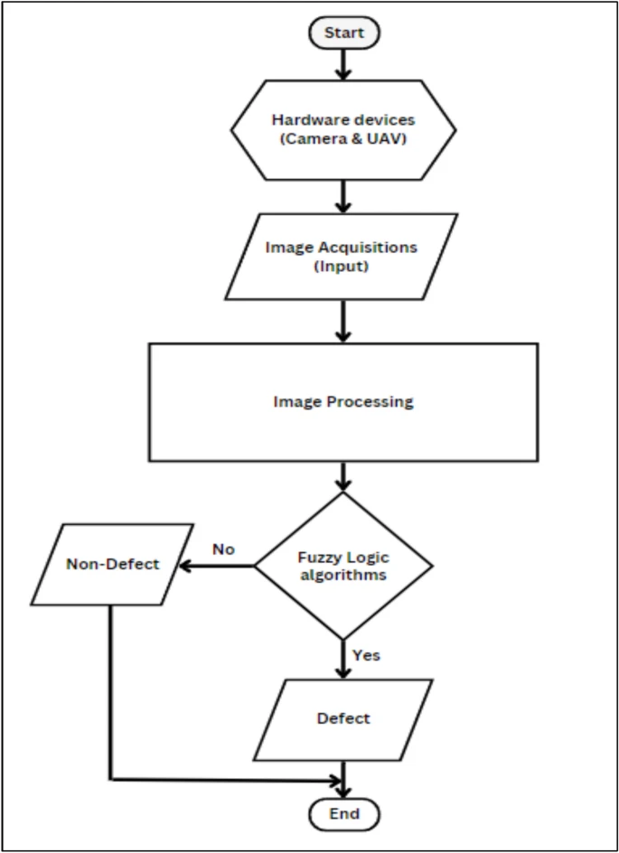 Automatic visual inspection procedure for the aircraft surfaces defects detection.
(Full size image)
Automatic visual inspection procedure for the aircraft surfaces defects detection.
(Full size image)
Image processing-based defect detection
Image frames are acquired from video (1 frame per 60 fps). These images are processed in three stages to detect defects: pre-processing, processing, and post-processing (Fig. 2).
Fig. 2
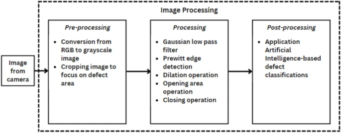 Stages in image processing.
(Full size image)
Stages in image processing.
(Full size image)
Image pre-processing
This stage prepares the image for further processing:
- Acquire and upload the image to MATLAB workspace.
- Convert RGB image to grayscale to reduce processing time.
- Crop the grayscale image to a 400x400 pixel square window focusing on potential defect areas, reducing image size and processing time.
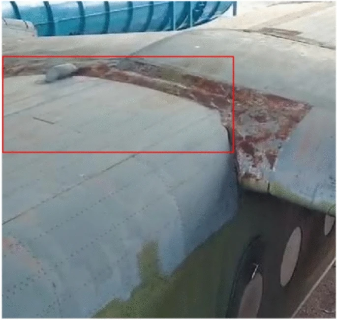
Fig. 3 shows these operations.
Fig. 3
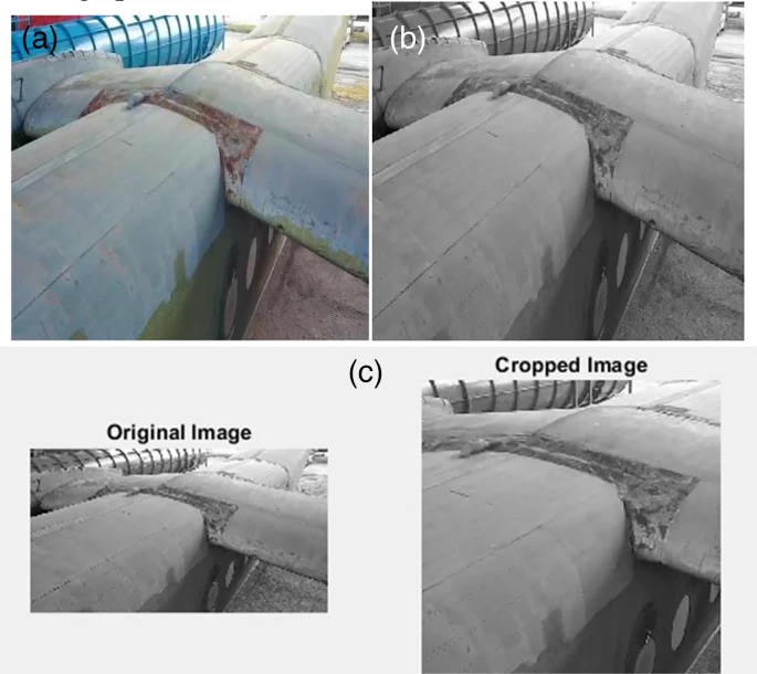 Reprocessing operations of the image: (a) Sample of surface aircraft defect (b) Image output after RGB to grayscale conversion (c) Comparison between before and after cropped image.
(Full size image)
Reprocessing operations of the image: (a) Sample of surface aircraft defect (b) Image output after RGB to grayscale conversion (c) Comparison between before and after cropped image.
(Full size image)
Image processing
Features of possible defects, non-defects, and noise are extracted using filters:
- Gaussian low pass filter: Removes high-frequency content like noise and sharp edges by smoothing the image (3x3 matrix, sigma value of 2). (Fig. 4a)
- Prewitt edge detection filter: Detects defect borders by calculating image intensity gradient. Applied to binary image. (Fig. 4b). Compared to Canny (Fig. 4c) and Sobel (Fig. 4d), Prewitt offers clearer edges for this application.
- Morphological dilation: Increases object area by adding pixels to boundaries, using a flat disk-shaped structuring element (3-unit radius). (Fig. 4e)
- 2-D order-statistic filtering (ordfilt2): Replaces each pixel with the 'order' element from its sorted neighborhood (order 15 pixels, domain true) to remove small objects remaining after dilation. (Fig. 4f)
- Morphological opening: Removes connected components with fewer than a threshold number of pixels (threshold 500 pixels, 4-connected neighborhood). (Fig. 4g)
- Morphological closing: Combines dilation and erosion to close small holes/gaps and smooth boundaries, using a flat disk-shaped structuring element (10-unit radius). (Fig. 4h)
- Image inversion: Inverts binary image (features black, background white) for visual comparison. (Fig. 4i)
Fig. 4
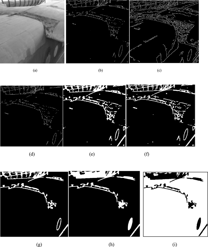 Results of image processing algorithm: (a) Gaussian low pass filter (b) Prewitt filter (c) Canny filter (d) Sobel filter (e) dilation operation on image (f) 2-D order-statistic filtering, (g) opening operation on image (h) closing operation on image (i) inversion of image.
(Full size image)
Results of image processing algorithm: (a) Gaussian low pass filter (b) Prewitt filter (c) Canny filter (d) Sobel filter (e) dilation operation on image (f) 2-D order-statistic filtering, (g) opening operation on image (h) closing operation on image (i) inversion of image.
(Full size image)
Noise cannot be entirely removed by image processing alone due to its unpredictable nature. An AI-based decision-making step is necessary. Fig. 5 shows an image after pre-processing and processing.
Fig. 5
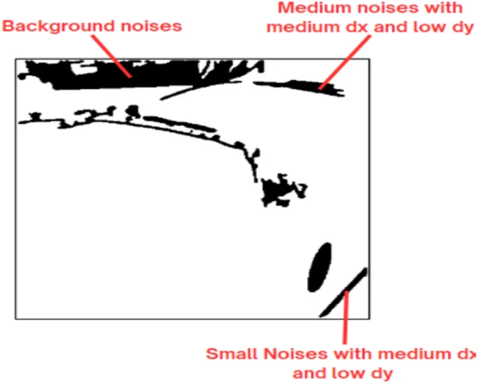 Defects on the image after image pre-processing and processing algorithm.
(Full size image)
Defects on the image after image pre-processing and processing algorithm.
(Full size image)
AI-based post-processing of image
Extracted features can be mixed with noise, leading to incorrect defect classification. Noise patterns are unpredictable (aircraft background, rivets, shadows). A two-stage AI algorithm is used to eliminate noise and make correct decisions.
- 1st Stage (Fuzzy Logic): Eliminates high-level noise like thin lines (straight or curved) resulting from edge detection. This noise is handled with low overlapping linguistic variables.
- 2nd Stage (Optimized Laser Simulator Logic - OLSL): Classifies features into defects or noise, removing small-area noises and shadow-like appearances. This low-level noise is handled with high overlapping linguistic variables.
1st stage of AI using fuzzy logic
Fuzzy logic rules are developed based on defect/noise characteristics (size, position, shape). Inputs (linguistic variables) are fuzzified, processed by rules, and the output is defuzzified to a crisp value. (Fig. 6)
Fig. 6
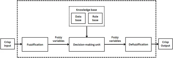 Fuzzy logic processes.
(Full size image)
Fuzzy logic processes.
(Full size image)
This stage eliminates thin line noise by measuring dx (horizontal major axis length) and dy (vertical minor axis length) for each feature (Fig. 7a, b). Inputs for the 1st fuzzy algorithm are dx and dy, each with linguistic variables {low, medium, high} (Table 2).
Fig. 7
 Features in 1st stage of fuzzy logic: (a) Horizontal distance of each features (dx) (b) Vertical distance of each features (dy).
(Full size image)
Features in 1st stage of fuzzy logic: (a) Horizontal distance of each features (dx) (b) Vertical distance of each features (dy).
(Full size image)
Table 2 Inputs and outputs linguistic variables sets ranges in the 1st fuzzy logic. (Full size table)
The output is 'Condition' {Small Noise, Medium Noise, Defect/Big Noise}. Membership functions are shown in Fig. 8. Rules are in Table 3.
Fig. 8
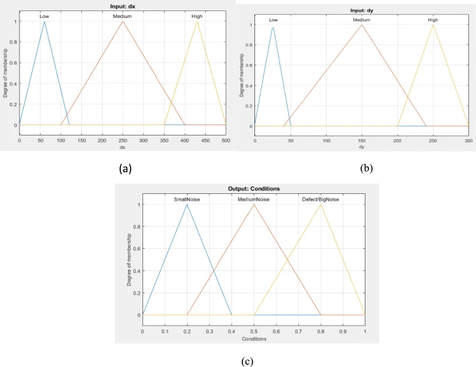 Fuzzy set of the 1st stage algorithm: (a) input fuzzy set (dx); (b) input fuzzy set (dy); (c) output fuzzy set (Condition).
(Full size image)
Fuzzy set of the 1st stage algorithm: (a) input fuzzy set (dx); (b) input fuzzy set (dy); (c) output fuzzy set (Condition).
(Full size image)
Table 3 1st fuzzy logic rules. (Full size table)
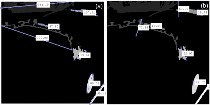
Features with crisp output between 20% and 70% (medium noise) are eliminated (Fig. 9). This narrows features to small noise and big noise/defect.
Fig. 9
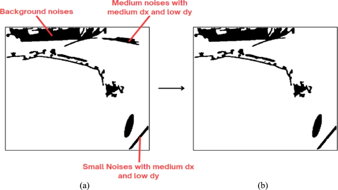 Result of the 1st stage using Fuzzy Logic Process: (a) before 1st stage of fuzzy logic (b) after 1st stage of fuzzy logic.
(Full size image)
Result of the 1st stage using Fuzzy Logic Process: (a) before 1st stage of fuzzy logic (b) after 1st stage of fuzzy logic.
(Full size image)
2nd Stage of AI using optimized laser simulator logic (OLSL)
This stage differentiates remaining features into noise or defect using area and perimeter as inputs. OLSL is an extension of Laser Simulator Logic, handling noise through high inference of linguistic variables with dynamic membership function ranges. It normalizes linguistic variables in highly overlapping zones, ensuring the sum of membership values is <= 1 (Figs. 10-13). Flowchart is in Fig. 11.
Fig. 10
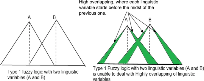 Fuzzy logic drawbacks with high overlapping.
(Full size image)
Fuzzy logic drawbacks with high overlapping.
(Full size image)
Fig. 11
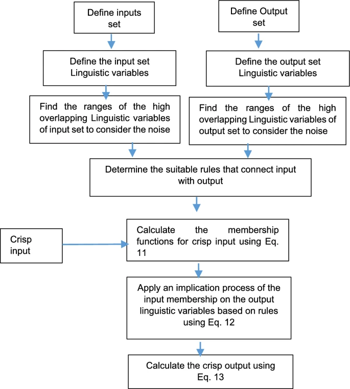 Shows the procedure of OLSL implementation.
(Full size image)
Shows the procedure of OLSL implementation.
(Full size image)
Fig. 12
 Inference system for a single linguistic variable in laser simulator logic.
(Full size image)
Inference system for a single linguistic variable in laser simulator logic.
(Full size image)
Fig. 13
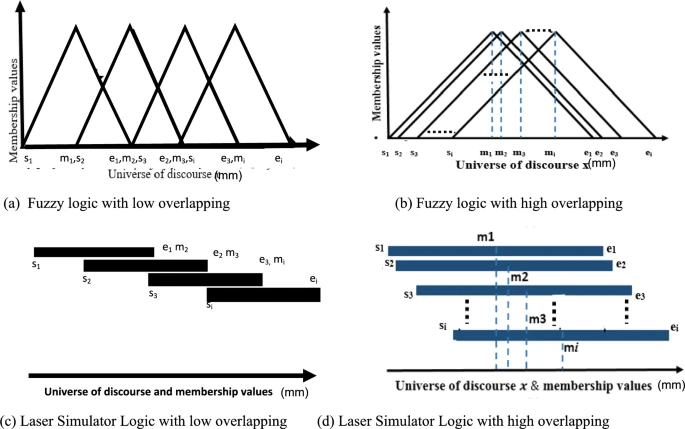 Types of Overlapping in membership functions for triangular fuzzy logic and Laser simulator.
(Full size image)
Types of Overlapping in membership functions for triangular fuzzy logic and Laser simulator.
(Full size image)
Principle of Optimized Laser Simulator Logic: OLSL simplifies computation for high inference linguistic variables compared to LSL. Key features include new step functions for non-occurrence (Eqs. 8, 9), a step function for any overlap (Eq. 10), and a general equation for membership values (Eq. 11).
Mathematical model of Optimized Laser Simulator Logic (OLSL): [Equation 1 showing the calculation of membership value μ(x) based on conditions involving x, s, m, e, a, b was presented here.] (1)
For x = y1 and x = y2, memberships are: μ(y1) = (y1 - s) / ((y1 - s) + (m - y1)), μ(y2) = (e - y2) / ((e - y2) + (y2 - m))
The accumulative membership values must satisfy: [Equation 2: Sum of μ_i(x) from i=1 to j is less than or equal to 1 for x in X.] (2)
[Equation 3 showing the accumulative membership values for lowly overlapping situations was presented here.] (3)
[Equation 4 showing the accumulative membership values for highly overlapping cases was presented here.] (4)
where ΔD is: [Equation 5 detailing the calculation of ΔD based on sub-ranges was presented here.] (5)
This is refined using: min((x - s_i), (e_i - x)) = { x - s_i if s_i < x < m_i; e_i - x if m_i < x < e_i } (6)
So, ΔD becomes: [Equation 7 redefining ΔD using the min function for sub-ranges was presented here.] (7)
A step function f_i eliminates non-occurring linguistic variables: f_i = { 1 if min((x - s_i), (e_i - x)) >= 0; 0 if min((x - s_i), (e_i - x)) < 0 } (8)
To nullify their effect: f_i * min((x - s_i), (e_i - x)) = { min((x - s_i), (e_i - x)) if x >= s_i; 0 if x < s_i } (9)
A step function N_x handles low vs. high inferencing: N_x = { 1 if x <= s_1 or x >= e_j-1; 0 if s_1 < x < e_j-1 } (10)
General equation for membership values: [Equation 11 providing a general formula for μ_i(x) for both low and high inference linguistic variables was presented here.] (11)
Implication and Defuzzification of OLSL: Implication: z_i = μ_i(x) * Z_i (12) Crisp output: z = (Sum of z_i from i=1 to n) / n (13)
Implementation of the proposed AI: Input set 1: Area = {Small, Average, Big} (0 to 10,000 pixels) Input set 2: Perimeter = {Low, Medium, High} (0 to 2000 pixels) Output: Object state = {Defect, Noise} Table 4 shows ranges. OLSL inputs are outputs of 1st fuzzy logic (>70% or <20%). Membership functions in Fig. 14. Rules in Table 5.
Table 4 Inputs and outputs linguistic variables ranges in 2nd stage using OLSL. (Full size table)
Fig. 14
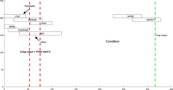 OLSL Membership input and output functions in the 2nd stage algorithm: (a) input fuzzy set (Area); (b) input fuzzy set (Perimeter); (c) output fuzzy set (Condition).
(Full size image)
OLSL Membership input and output functions in the 2nd stage algorithm: (a) input fuzzy set (Area); (b) input fuzzy set (Perimeter); (c) output fuzzy set (Condition).
(Full size image)
Table 5 OLSL rules. (Full size table)
Crisp output < 50% is eliminated (noise). Fig. 15 shows results. Background and low noises are removed.
Fig. 15
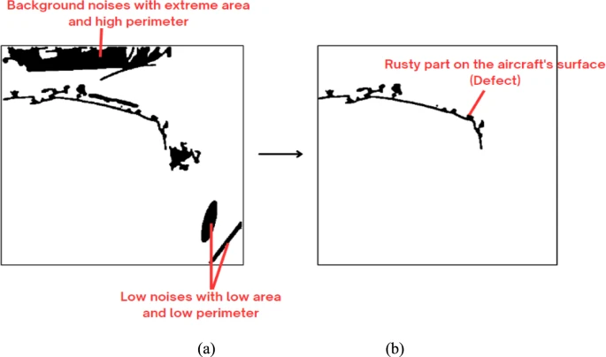 Result of 2nd stage using OLSL algorithm: (a) before 2nd stage using OLSL (b) after 2nd stage using OLSL.
(Full size image)
Result of 2nd stage using OLSL algorithm: (a) before 2nd stage using OLSL (b) after 2nd stage using OLSL.
(Full size image)
Detected defects can be shown with a bounding box (Fig. 16).
Fig. 16
 Output image with bounding box surrounding the possible detected defect.
(Full size image)
Output image with bounding box surrounding the possible detected defect.
(Full size image)
Comparison with YOLO11 trained on ROBOFLOW dataset
The proposed FL-OLSL algorithm was compared with YOLO11 trained on the ROBOFLOW aircraft skin defects dataset (372 images, 5 defect classes). Applied to Fig. 3a, YOLO11 found no defects (Fig. 17a). Fig. 17b shows YOLO11 detecting a defect.
Fig. 17
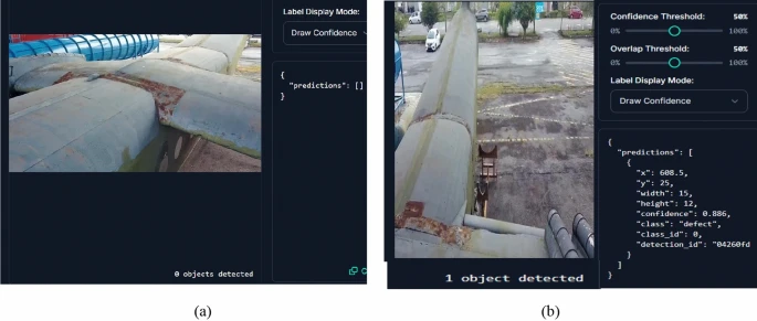 Results of Yolo11 with ROBOFLOW dataset: (a) the result of original image as in Fig. 3a. (b) model result with one defect on the surface.
(Full size image)
Results of Yolo11 with ROBOFLOW dataset: (a) the result of original image as in Fig. 3a. (b) model result with one defect on the surface.
(Full size image)
Results and discussions
Misclassifications can occur due to:
- Lighting variations: Shadows or reflections mistaken for defects. Homogeneous lighting could solve this.
- Image noise: Random pixel variations resembling defects. Multiple cameras or depth sensors could confirm defects.
- Occlusion: Hidden parts misinterpreted as defects. Image registration from multiple views could help.
Image distortions from drone vibration, handling, or camera performance in heat can also cause misclassifications. Distortion removal algorithms can be applied.
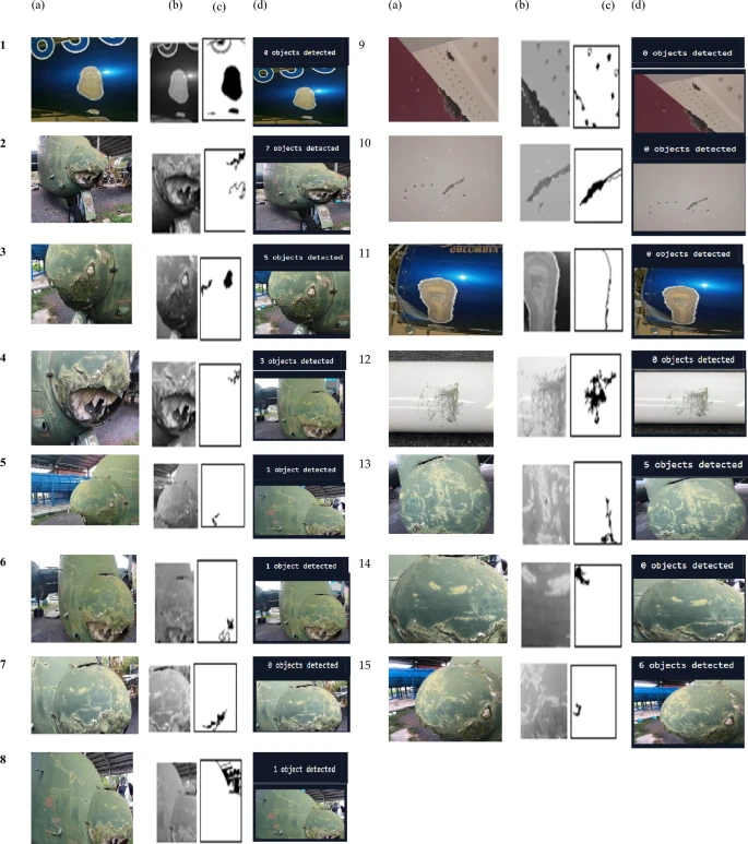
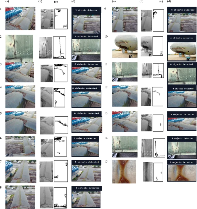
Sixty experiments were conducted for cracks, dents, scratches, and rust (Figs. 18-21) under various environmental conditions. Each run used the proposed algorithm and YOLO11. Fifteen images per defect type were evaluated.
Fig. 18
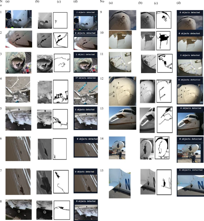 Results of cracks inspection for 15 samples of aircraft surface inspection: (a) original (b) image processing (c) OLSL + FL (d) Yolo 11.
(Full size image)
Results of cracks inspection for 15 samples of aircraft surface inspection: (a) original (b) image processing (c) OLSL + FL (d) Yolo 11.
(Full size image)
Fig. 19
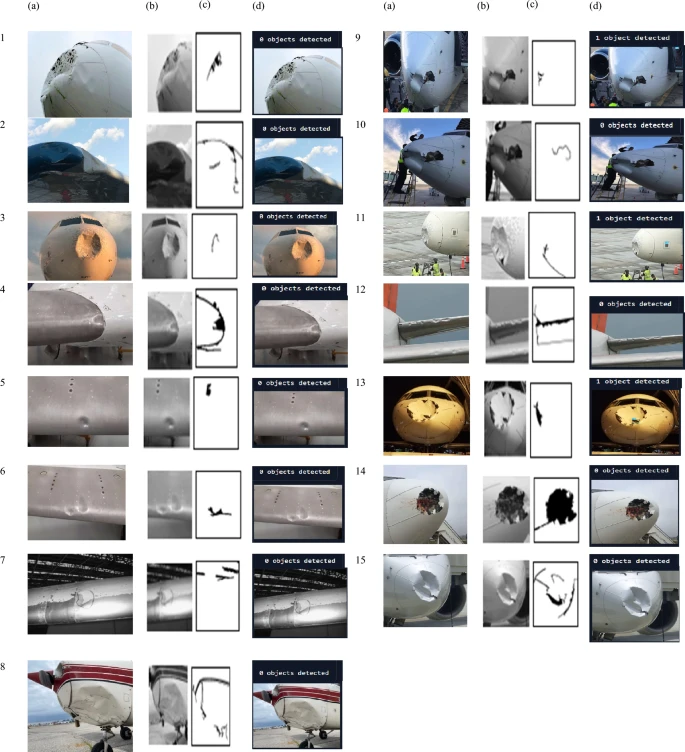 Results of dent inspection for 15 samples of aircraft surface inspection: (a) original (b) image processing (c) OLSL + FL (d) Yolo 11.
(Full size image)
Results of dent inspection for 15 samples of aircraft surface inspection: (a) original (b) image processing (c) OLSL + FL (d) Yolo 11.
(Full size image)
Fig. 20
 Results of scratches inspection for 15 samples of aircraft surface: (a) original (b) image processing (c) OLSL + FL (d) Yolo 11.
(Full size image)
Results of scratches inspection for 15 samples of aircraft surface: (a) original (b) image processing (c) OLSL + FL (d) Yolo 11.
(Full size image)
Fig. 21
 Results of rust inspection for 15 samples of aircraft surface: (a) original (b) image processing (c) OLSL + FL (d) Yolo 11.
(Full size image)
Results of rust inspection for 15 samples of aircraft surface: (a) original (b) image processing (c) OLSL + FL (d) Yolo 11.
(Full size image)
Table 6 shows results for 15 trials.
Table 6 Evaluations of defect detection using 60 samples for cracks, dents, scratches and rust defects for proposed method (OLSL + FL) and Yolo 11. (Full size table)
Graphs of true detection consistency (Figs. 22-25).
Fig. 22
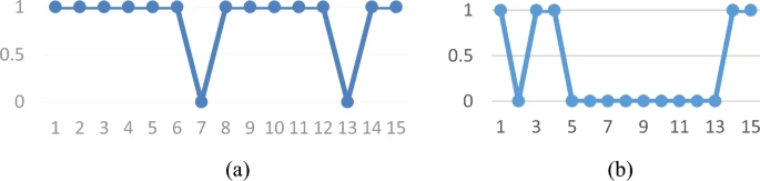 Graph of cracks output detection against 15 samples: (a) proposed algorithm (OLSL + FL) (b) Yolo 11.
(Full size image)
Graph of cracks output detection against 15 samples: (a) proposed algorithm (OLSL + FL) (b) Yolo 11.
(Full size image)
Fig. 23
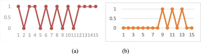 Graph of dents output detection against 15 samples: (a) proposed algorithm (OLSL + FL) (b) Yolo 11.
(Full size image)
Graph of dents output detection against 15 samples: (a) proposed algorithm (OLSL + FL) (b) Yolo 11.
(Full size image)
Fig. 24
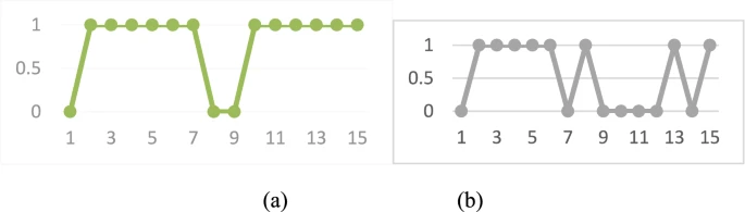 Graph of scratches output detection against 15 samples: (a) proposed algorithm (OLSL + FL) (b) Yolo 11.
(Full size image)
Graph of scratches output detection against 15 samples: (a) proposed algorithm (OLSL + FL) (b) Yolo 11.
(Full size image)
Fig. 25
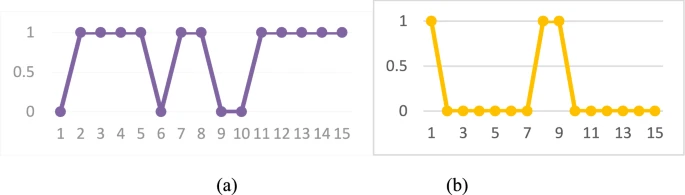 Graph of rust output detection against 15 samples: (a) proposed algorithm (OLSL + FL) (b) Yolo 11.
(Full size image)
Graph of rust output detection against 15 samples: (a) proposed algorithm (OLSL + FL) (b) Yolo 11.
(Full size image)
Five metrics were calculated: Precision (P), Recall (TPR), False Positive Rate (FPR), F-score, Accuracy (AC). [Equation 14: P = TP / (TP + FP)] (14) [Equation 15: TPR = TP / (TP + FN)] (15) [Equation 16: FPR = FP / (FP + TN)] (16) [Equation 17: F = 2 / (P^-1 + TPR^-1)] (17) [Equation 18: AC = (TP + TN) / (TP + FP + FN + TN)] (18)
Values for TP, FP, FN, TN: Cracks: proposed: TP=11, FP=1, FN=1, TN=2; Yolo: TP=4, FP=5, FN=5, TN=1. Dents: proposed: TP=9, FP=3, FN=2, TN=1; Yolo: TP=3, FP=6, FN=6, TN=0. Scratches: proposed: TP=10, FP=2, FN=2, TN=2; Yolo: TP=6, FP=4, FN=3, TN=2. Rust: proposed: TP=9, FP=2, FN=2, TN=2; Yolo: TP=2, FP=9, FN=3, TN=1.
Metric results in Table 7.
Table 7 Shows the metrics values of the proposed algorithm and Yolo 11 for each type of defect. (Full size table)
The proposed algorithm outperforms YOLO11 across all metrics, likely because YOLO11 was trained on insufficient data (372 images). Precision for the proposed algorithm is 0.75-0.92; for YOLO11, 0.18-0.60. Recall is high for proposed (0.81-1); YOLO11 recall is poor except for scratches. F-score averages 83% for proposed, 40% for YOLO11. Accuracy (AC) is better for the proposed algorithm; YOLO11 struggles with medium/big defects.
Accuracy for dents (66.67%) is lower due to their subtle visual impact. Advanced techniques like 3D imaging or multiple cameras could improve dent detection. Cracks (86%) and scratches (80%) are detected well. Rust detection (76.67%) is affected by similarity to noise.
To improve efficiency:
- Use a homogeneous lighting system with the drone.
- Employ 3D imaging, multiple cameras, or depth sensors.
- Register images from different angles.
- Apply distortion removal algorithms.
Practical implications, ethical and safety of UAV deployment in aviation maintenance
The proposed system can replace human inspection, reducing inspection time and airline waiting times. Aircraft-on-ground (AOG) operations are costly ($10,000-$150,000 per incident). Drone-based inspection can be more efficient and accurate.
Privacy and ethics are barriers; drone use near airports (within 5km) is often prohibited. Controlled drone flight near airlines poses no safety problem. Currently, no specific regulations govern UAV operations for aircraft inspections in airports.
Conclusion
This study significantly contributes to automatic visual inspection of aircraft external surfaces using a drone with a Wi-Fi camera. An image processing algorithm extracts features, and a cascading OLSL and fuzzy logic algorithm eliminates noise. The proposed algorithm handles noise via high overlapping linguistic variables. Tested on 60 samples, it achieved accuracy rates of 86.67% (cracks), 66.67% (dents), 80.0% (scratches), and 76.67% (rust), outperforming YOLO11 trained on ROBOFLOW (accuracies: 33%, 20%, 53%, 20% respectively). The system will shorten pre-flight check times and improve inspection efficiency by reducing human error.
Future work
Potential future tasks:
- Explore detection of additional defects like dirt and paint detachment.
- Enhance the algorithm with 3D imaging or multi-camera systems for better dent and rust detection.
- Test on in-service aircraft.
- Develop a dashboard and GUI for data visualization to aid inspection specialists.
Data availability
All data generated or analysed during this study are included in this article.
References
- Pant, S., Sharif Khodaei, Z. & Droubi, M. G. Monitoring tasks in aerospace. In Structural Health Monitoring Damage Detection Systems for Aerospace. Springer Aerospace Technology (eds Sause, M. G. R. & Jasiūnienė, E.) (Springer, 2021). (Google Scholar)
- Sause G. and Jasiūnienė E. Structural Health Monitoring Damage Detection Systems for Aerospace Springer Aerospace Technology Springer Cham Springer Nature XII 284. https://doi.org/10.1007/978-3-030-72192-3 (2021).
- Faisal, N. et al. Defect types. In Structural Health Monitoring Damage Detection Systems for Aerospace. Springer Aerospace Technology (eds Sause, M. G. R. & Jasiūnienė, E.) (Springer, 2021). (Google Scholar)
- Ai, L., Soltangharaei, V., Bayat, M., VanTooren, M. & Ziehl, P. Detection of impact on aircraft composite structure using machine learning techniques. Meas. Sci. Technol. 32, 084013. https://doi.org/10.1088/1361-6501/abe790 (2021). (Article ADS CAS Google Scholar)
- Avdelidis, P. et al. Defects recognition algorithm development from visual UAV inspections. Sensors 22, 4682. https://doi.org/10.3390/s22134682 (2022). (Article ADS CAS PubMed PubMed Central Google Scholar)
- Das, S., Hollander, D. & Suliman, S. Automating visual inspection with convolutional neural networks. In Annual Conference of the PHM Society Vol. 11. https://doi.org/10.36001/phmconf.2019.v11i1.868 (2019).
- Bugaj, M., Novák, A., Stelmach, A. & Lusiak, T. Unmanned aerial vehicles and their use for aircraft inspection. In 2020 New Trends in Civil Aviation (NTCA) 45–50. https://doi.org/10.23919/NTCA50409.2020.9290929. (2020).
- Zhou, M., Zuo, H., Xu, J. & Qian, C. An intelligent detection method for civil aircraft skin damage based on YOLOv3. In Proceedings of the 3rd Asia-Pacific Conference on Image Processing, Electronics and Computers 586–590. https://doi.org/10.1145/3544109.354431 (2022).
- Mian, S., Garrett, T., Glandon, A., Manderino, C., Balachandran, S., Munoz, A. & Dolph, V. Autonomous spacecraft inspection with free-flying drones. In 2020 AIAA/IEEE 39th Digital Avionics Systems Conference (DASC) 1–9. https://doi.org/10.1109/DASC50938.2020.9256569 (2020).
- Silberberg, P. & Leishman, C. Aircraft inspection by multirotor UAV using coverage path planning. In International Conference on Unmanned Aircraft Systems (ICUAS) 575–581. https://doi.org/10.1109/ICUAS51884.2021.9476718 (2021).
- Ruiqian, L., Juan, X. & Hongfu, Z. Automated Surface defects acquisition system of civil aircraft based on unmanned aerial vehicles. 2020 IEEE 2nd International Conference on Civil Aviation Safety and Information Technology (ICCASIT) 729–733. https://doi.org/10.1109/ICCASIT50869.2020.9368540 (2020).
- He, B., Huang, B., Lin, Y. & Wu, L. Intelligent unmanned aerial vehicle (UAV) system for aircraft surface inspection. 7th International Forum on Electrical Engineering and Automation (IFEEA) 316–321. https://doi.org/10.1109/IFEEA51475.2020.00073 (2020).
- Ramalingam, B. et al. Visual inspection of the aircraft surface using a teleoperated reconfigurable climbing robot and enhanced deep learning technique. Int. J. Aerosp. Eng. 2019, 5137139. https://doi.org/10.1155/2019/5137139 (2019). (Article Google Scholar)
- Amarathunga, A. I. et al. A robotic platform for aircraft composite structure inspection using thermography. Robotics 11, 62. https://doi.org/10.3390/robotics11030062 (2022). (Article Google Scholar)
- Liu, Y., Dong, J., Li, Y., Gong, X. & Wang, J. A UAV-based aircraft surface defect inspection system via external constraints and deep learning. IEEE Trans. Instrum. Meas. 71(1–15), 200. https://doi.org/10.1109/TIM.2022.319871 (2022). (Article Google Scholar)
- Wu, B., Ding, Y., Ding, M. & Xu, J. Aircraft skin damage detection method based on improved mask scoring R-CNN. In 6th International Conference on Information Science Computer Technology and Transportation 1–5. https://ieeexplore.ieee.org/document/9738947 (2021).
- Wu, S. & Li, Y. Edge-based realtime image object detection for UAV missions. In 30th Wireless and Optical Communications Conference (WOCC) 293–294. https://doi.org/10.1109/WOCC53213.2021.9602868 (2021).
- Ali, M. A. H. & Lun, A. K. A cascading fuzzy logic with image processing algorithm–based defect detection for automatic visual inspection of industrial cylindrical object’s surface. Int. J. Adv. Manuf. Technol. 102, 81–94. https://doi.org/10.1007/s00170-018-3171-7 (2019). (Article Google Scholar)
- Ali, M. A. H., Mekhilef, S., Yusoff, N. & Abd, R. B. Laser simulator logic: A novel inference system for highly overlapping of linguistic variable in membership functions. J. King Saud Univ. Comput. Inf. Sci. 34, 8019–8040. https://doi.org/10.1016/j.jksuci.2022.07.017 (2022). (Article Google Scholar)
- DDIISc. aircraft_skin_defects dataset, Roboflow Universe, Roboflow, visited on 2025-03-10. https://universe.roboflow.com/ddiisc/aircraft_skin_defects (2023).
- Marx Jr, C. Aircraft on Ground. https://www.linkedin.com/pulse/aircraft-ground-chuck-marx#:~:text=The%20costs%20to%20an%20airline,this%20cost%20adds%20up%20quickly (2023).
Acknowledgements
Authors would like to thank University of Malaya and Ministry of High Education-Malaysia for supporting this work via Fundamental Research Grant Scheme (FRGS/1/2023/TK10/UM/02/3 and GPF020A-2023).
Author information
Authors and Affiliations
- Department of Mechanical Engineering Faculty of Engineering, University of Malaya, 50603, Kuala Lumpur, Malaysia Mohammed A. H. Ali, Muhammad Zamil A. Zulkifle, Nik Nazri Nik Ghazali & M. M. F. Meor Zulkifli
- Department of Engineering, Faculty of Advanced Technology and Multidiscipline, Universitas Airlangga, Surabaya, 60115, Indonesia Nik Nazri Nik Ghazali & Retna Apsari
- Department of Physics, Faculty of Science and Technology, Universitas Airlangga, Surabaya, 60115, Indonesia Retna Apsari
- Mechanical and Industrial Engineering Department, Abu Dhabi University, Zayed City, 59911, Abu Dhabi, United Arab Emirates Mohammad Alkhedher
Authors
- Mohammed A. H. Ali (PubMed Google Scholar)
- Muhammad Zamil A. Zulkifle (PubMed Google Scholar)
- Nik Nazri Nik Ghazali (PubMed Google Scholar)
- Retna Apsari (PubMed Google Scholar)
- M. M. F. Meor Zulkifli (PubMed Google Scholar)
- Mohammad Alkhedher (PubMed Google Scholar)
Contributions
M.A.H.A., and M.Z.A.Z, Conceptualization; M.A.H.A. and M.Z.A.Z, Data curation; M.A.H.A., M.Z.A.Z., N.N.N.G., R.A., Formal analysis; M.A.H.A., N.N.N.G. and M.A., Funding acquisition; M.A.H.A., N.N.N.G., M.Z.A.Z and M.M.F.M., Investigation; M.A.H.A., and M.Z.A.Z., Methodology; M.A.H.A. Project administration; M.A.H.A., Resources; M.A.H.A., M.Z.A.Z. and M.A. Software; M.A.H.A., Supervision; M.A.H.A., M.Z.A.Z, N.N.N.G., R.A., M.M.F.M. and M.A., Validation ; M.A.H.A. and M.Z.A.Z., Visualization; M.A.H.A. Writing—original draft; M.A.H.A., N.N.N.G., R.A., M.M.F.M and M.A., Writing—review and editing. All authors have read and agreed to the published version of the manuscript.
Corresponding author
Correspondence to Mohammed A. H. Ali.
Ethics declarations
Competing interests
The authors declare no competing interests.
Additional information
Publisher’s note
Springer Nature remains neutral with regard to jurisdictional claims in published maps and institutional affiliations.
Rights and permissions
Open Access This article is licensed under a Creative Commons Attribution-NonCommercial-NoDerivatives 4.0 International License, which permits any non-commercial use, sharing, distribution and reproduction in any medium or format, as long as you give appropriate credit to the original author(s) and the source, provide a link to the Creative Commons licence, and indicate if you modified the licensed material. You do not have permission under this licence to share adapted material derived from this article or parts of it. The images or other third party material in this article are included in the article’s Creative Commons licence, unless indicated otherwise in a credit line to the material. If material is not included in the article’s Creative Commons licence and your intended use is not permitted by statutory regulation or exceeds the permitted use, you will need to obtain permission directly from the copyright holder. To view a copy of this licence, visit http://creativecommons.org/licenses/by-nc-nd/4.0/.
About this article
Cite this article
Ali, M.A.H., Zulkifle, M.Z.A., Nik Ghazali, N.N. et al. AI-driven UAV with image processing algorithm for automatic visual inspection of aircraft external surface. Sci Rep 15, 19581 (2025). https://doi.org/10.1038/s41598-025-02902-2
- Received: 24 December 2024
- Accepted: 16 May 2025
- Published: 04 June 2025
- DOI: https://doi.org/10.1038/s41598-025-02902-2
Compare Plans & Pricing
Find the plan that matches your workload and unlock full access to ImaginePro.
| Plan | Price | Highlights |
|---|---|---|
| Standard | $8 / month |
|
| Premium | $20 / month |
|
Need custom terms? Talk to us to tailor credits, rate limits, or deployment options.
View All Pricing Details